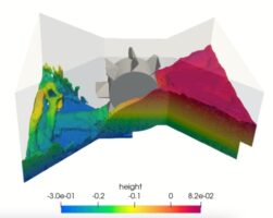
water turbine
Water turbines are often used in hydroelectric power plants. The turbine has the function of changing the potential energy possessed by the water into mechanical energy (rotation) in the turbine rotor. The mechanical energy of the turbine is connected to a generator to generate electricity.
The working principle of a water turbine is the utilization of the potential energy of water to rotate the turbine blades. The water will be sprayed into the blade with high pressure so that it rotates the blade. The blade rotation will automatically rotate the turbine shaft. The rotation of the turbine shaft is forwarded to the generator shaft to generate electrical energy from the mechanical energy of the turbine.
The types of water turbines that are often used in the field are:

- Pelton Turbine: The main feature of this turbine is the blade shape like a spoon and a nozzle. With the help of the nozzle and the large capacity of the blade water, the Pelton turbine is suitable for high heads.
- Cross-flow Turbine: The main characteristic of this turbine is the shape of the runner (blades) that extends into a cylindrical shape. This turbine is suitable for low head.
- Francis Turbine: The main feature of this turbine is that its shell is shaped like a snail’s shell or shaped like a centrifugal pump. This turbine is suitable for medium-high head operation.
- Kaplan Turbine: The main feature of this turbine is the axial direction of water flow and the shape of the propeller like the propeller on a boat.
The design of a water turbine requires calculation formulas that must be considered. The calculations that are most often used as references are flow rate and head.
The flow rate is the volume of water flowing per unit second. Flow rate are generally formulated as:
Q=V.A
- Q = Flow rate (m3/s)
- V = Water flow rate (m/s)
- A = Flow cross-sectional area (m2)
Head is the flow energy per unit weight that occurs at the inlet or outlet flow. Head is expressed as a unit of distance so that the physical phenomenon of the head is the flow distance that can be reached by a fluid. Bernoulli’s equation states that the total inlet head on the turbine will be equal to the total outlet head. In general it can be written as:

However in reality, it cannot be that simple for water turbine design because usually we need some kind of prototype to test the quality of the water turbine and this method will waste a lot of money and time for testing. In modern times, there is a method called the CFD (computational Fluid Dynamics) simulation method to test fluid flow in the design of our engineering equipment using a computer.
>>> LEARN MORE ABOUT CFD SIMULATION METHOD ON WATER TURBINE !
Contributor: Daris Arsyada
References:
https://ilmuteknik.id/jenis-jenis-turbin-air-beserta-cara-kerjanya/
https://slideplayer.info/amp/11996944/


Leave a Reply
Want to join the discussion?Feel free to contribute!