wind turbine blade design
The use of wind as an energy source has been used for hundreds of years to pump water or grind corn, this equipment is also known as a windmill. In the 19th century, fossil fuels replaced the use of these large, heavy, inefficient windmills. Then, knowledge of aerodynamics and lightweight materials brought back wind turbine technology around the 20th century.
Based on the orientation of the direction of rotation of the axis, these wind turbines are divided into two categories: Horizontal Axis Wind Turbine (HAWT) dan Vertical Axis Wind Turbine (VAWT).

Each configuration has advantages and disadvantages. In general, VAWT development began to decline due to the limitations of the VAWT at low speed operating conditions and the difficulty of controlling the rotor speed, this design also has difficulties in its starting . However, VAWT has the advantage that it does not require additional mechanisms and a large generator can be used because it is not limited by the use of high towers. The development of HAWT is increasingly popular because of the increase in performance and control can be done with pitch and yaw control.
THEORY MAXIMUM EFFICIENCY
High rotor efficiency is desirable to increase the conversion of wind flow energy into mechanical energy of the rotor, surely with affordable production costs. To calculate its efficiency, it is first necessary to define the incoming wind power (potential energy):

Where,
P = Power (watt)
ρ = Air density (kg/m3)
A = Turbin area (m2)
V = Velocity (m/s)
The air flow through the wind turbine will drop its velocity due to the interaction between the air and the turbine, the velocity drop also indicates a change in wind energy into mechanical energy of the rotor. If we want 100% efficiency, the wind speed after passing the turbine must be zero, or stop at all, definitely this is not possible; while it can be calculated using the rotor disc theory that the maximum efficiency that can be achieved theoretically is 59.3%, this efficiency parameter is called the power coefficient Cp, the maximum Cp = 0.593 also known as the Betz limit in wind turbine design.
The actual efficiency of the wind turbine will be reduced due to several factors such as the emergence of wake flow in the blades which reduces the lift on the airfoil, the selection of an airfoil that has low efficiency and the emergence of flow “leakage” at the tip which results in undesirable vortex flow.
To produce rotation (torque) on the wind turbine rotor, two methods are used, namely utilizing drag or using lift from the aerodynamic shape of the blade. Here is a comparison table of the two models:

For the Drag model, the wind turbine blades are intentionally made to block the air flow and are given a certain moment arm about the rotating axis, thereby producing torque to rotate the turbine. Another alternative is to use the aerodynamic lift that occurs on the airfoil rotor then the lift is directed in the direction of the rotation of the rotor and a moment arm is given to the axis of rotation to produce torque. The lift method tends to be more efficient because it does not change the airflow pattern much or produces a lot of wakes. Here are some types of wind turbines along with some of their descriptions:

BLADE HAWT DESIGN
The focus of the discussion in this article is HAWT because of its popularity in the wind turbine industry, this type of turbine is very sensitive to the design of the blade profile and its design. The first thing we must pay attention to in wind turbine design is the Tip Speed Ratio (TSR) parameter, this parameter is a comparison between the tangential speed of the tip blade to the speed of the incoming wind (free stream) which is mathematically written as follows:

Where,
λ = TSR
Ω = Rotation speed (rad/s)
r = Radius (m)
Vw = Wind velocity (m/s)
Aspects such as efficiency, torque, mechanical stress on the blade and noise should be considered in this TSR calculation. Modern wind turbines tend to be designed using a TSR value of around 6-9 because of the above considerations, in general the peak efficiency is at TSR = 7.
BLADE SHAPE CALCULATION
Based on the theory of Blade Element Momentum (BEM), which is the calculation of wind turbine performance based on the cross section or airfoil shape of each section of the blade calculated by dividing it into small elements in 2D. For blades with a design TSR of about 6-9, Betz’s momentum theory provides a fairly good approximation to calculating the blade profile shape with the following equation:

n = number of blades , CL = Airfoil Lift Coefficient, Vr = Resultant of Wind Velocity (m/s), U = Wind velocity (m/s), Uwd = Wind velocity design (m/s), Copt = Optimum Chord Length. The Copt can be plotted against r to produce the optimal “shape” of the blade.
From the above equation it can be seen that the larger the TSR, the smaller the blade size, then the more the number of blades, the smaller the blade size (see changes made to the root and tip to adjust the actual conditions both for installation on the hub and due to structural reasons, this can also be done because the power contribution of the root is also relatively low):

The smaller the blade size will be advantageous in terms of cost, because the material needed will be less, but on the other hand the blade structure will also be weaker. In general, the most optimal choice of blades is 3 pieces.
This approach is quite good for the initial design, but it is a 2D approach so it is not very accurate in considering the emergence of 3D phenomena or the appearance of wakes, tip losses and so on. For more accurate and comprehensive results, analysis using Computational Fluid Dynamics (CFD) simulation is used.

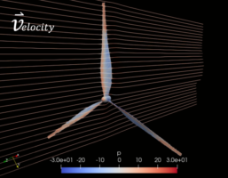
In the end, to analyze aerodynamic performance in 3D and comprehensively, we cannot just rely on the calculations of the approach above. One of the well-known methods in wind turbine design is the use of computational fluid dynamics (CFD) (read more in the introduction to CFD). This method is carried out using a computer to analyze the fluid flow on the wind turbine blade in detail to show 3D flow interactions and other features such as tip vortex, wake and others without simplification.
From the CFD simulation we can also predict the performance of the wind turbine such as calculating power coefficient and torque under various conditions of TSR variation and changes in twist angle, number of blades, airfoil variations, tip model variations and so on.
As for calculating the structural strength of the wind turbine blades, analytical equations alone are not sufficient, due to variations in materials and discontinuous forms of the blade frame and wind turbine tower. The method that is often used for this analysis is using Finite Element Analysis (FEA).

>> CLICK HERE TO DESIGN WIND TURBINE USING CFD METHOD!

aeroengineering services is a service under CV. Markom with solutions especially CFD/FEA.
References:
Peter J. Schubel * and Richard J. Crossley, “Wind turbine blade design“. Energies 2012, 5, 3425-3449; doi:10.3390/en5093425


Leave a Reply
Want to join the discussion?Feel free to contribute!